
Certified quality management system



Ground Bond Tester RS36A-25
€2,310.00*
Details
+49 421 277 9999
Product information "Ground Bond Tester RS36A-25"
The RS36A-25 is a protective earth (PE) test instrument using 4-wire measurement technology for test currents of 10 A AC or 25 A AC, with resistance limits from 1 to 300 mΩ (10 A range) or 1 to 200 mΩ (25 A range). The source and sense paths are routed separately, so the resistance of the measuring and connection leads does not affect the measurement result. The unit is suitable for stand-alone operation as well as remote control via PC software or customer-specific applications.
Highlights
- PE - protective earth test: 10 A AC or 25 A AC, 1 - 200 mΩ (25 A range), 1 - 300 mΩ (10 A range), 6 - 12 V, 4-wire measurement technology
- Shutdown via limit value and peak detection
- Ramp function, keypad lock, minimum current monitoring
- Remote controllable (ASCII, Windows DLL, .NET Framework Assembly, DataView)
- Source-sense operation, automatic start for test guns
- Contact and cable break monitoring
- 15 freely programmable parameter sets
- Fault indication: acoustic, optical and via interface
- Safety circuit with two positively driven safety relays
Electrical test: PE test 10 / 25 A AC, 300 / 200 mOhm
Test current |
|
| Adjustment range: | > 10 A AC and > 25 A AC |
| Resolution, digit: | 0.1 A |
| Measurement uncertainty, accuracy: | 1 % of reading +/- 2 digits |
| Waveform: | sinusoidal, mains dependent |
| Actual value display: | LED display 13 mm, red |
| Set value display: | LED display 10 mm, red |
Resistance |
|
| Adjustment range, limit: | 1 - 300 mΩ in the 10 A range 1 - 200 mΩ in the 25 A range |
| Resolution, digit: | 1 mΩ |
| Measurement uncertainty: | 1 % of reading +/- 2 digits |
| Actual value display: | LED display 13 mm, red |
| Set value display: | LED display 10 mm, red |
Test time |
|
| Test time adjustment range: | 1 s - 99 min, endless |
| Ramp time adjustment range: | 0.5 s - 99 s |
| Resolution up to 10 s: | 0.1 s (digit) |
| Display resolution > 10 s: | 1 s |
| Measurement uncertainty: | +/- 1 digit |
| Start of test time: | Test time only starts once the test current has been fully reached |
| Minimum test time: | 1 s |
| Actual value display: | LED display 13 mm, red |
| Set value display: | LED display 10 mm, red |
Housing, device data, environment & safety
General device data |
|
| Supply voltage: | 230 V, 50 Hz / 60 Hz |
| Mains connection: | Schuko plug |
| Supply voltage tolerance: | +/- 10 % |
| Current consumption: | max. 8 A |
| Fuse: | 8 A, T, 5 x 20 mm, 250 V |
| Displays: | LED, permanent display of set and actual values |
| Setting of test parameters: | manually or fully automatic via interface (Windows DLL, ASCII, .NET Framework Assembly, DataView) |
| Storage of test parameters: | 15 freely programmable parameter sets |
| Fault signalling: | acoustic, optical and via interface |
| Outputs on the front panel: | 2 x measuring connections for contacting the test object, optional rear connections |
| Dimensions (W x H x D): | 308 x 168 x 273 mm |
| Weight: | approx. 10.5 kg |
| Housing: | plastic, RAL 7035 |
| Standard scope of delivery: | operating instructions, mains cable |
| Calibration: | factory calibration incl. calibration certificate, DAkkS calibration optionally available |
Environmental conditions |
|
| Housing: | IP20 |
| Humidity: | max. 80 %, non-condensing |
| Permissible temperature range: | +5 to +40 °C |
| Max. altitude above sea level: | 2,000 m |
| Cooling: | passive, active cooling optionally available |
Electrical safety and standards |
|
| EN 61010-1: | Safety requirements for electrical equipment for measurement, control and laboratory use |
| EN 61326-1: | Electrical equipment for measurement, control and laboratory use – EMC requirements |
| EN 61000-3-3 / EN 61000-3-2: | Electromagnetic compatibility (EMC) |
| EN 50191: | Erection and operation of electrical test equipment |
| Pollution degree: | 2 |
| Protection class: | 1 |
Operation, start options & interfaces
Advanced device setup |
|
| Keypad lock: | individually configurable |
| Signal configurator: | individual configuration of the digital result outputs |
| Buzzer options: | individual configuration of the acoustic signals |
| LED display: | brightness of display elements adjustable |
| Start options: | individual configuration of start modes |
| Language and mode selection for external printer: | printout on PASS, FAIL, always or disabled; formats: strip printout or CSV format |
Start options for the test |
|
| Start button on the device: | Test start via button on the front panel |
| Start via serial interface: | Start triggered by a superordinate controller (PLC or PC) |
| Start via digital interface: | Start via digital I/O, e.g. PLC, foot switch, push button, etc. |
Interfaces |
|
| Control / digital I/O: | Digital interface for connecting a PLC, foot switch or a result/operating panel with signals such as start, stop, result PASS/FAIL and test running |
| RS232 / PC interface: | For connection to a PC. All test parameters can be set from the superordinate controller; the desired test set values are set automatically by the device. The interface also allows continuous data acquisition and status monitoring. On the PC side, the DataView data management package or a driver (Windows DLL, ASCII, .NET Framework Assembly) is available for own PC applications |
| RS232 / ASCII printout: | For direct connection to a terminal program or a protocol printer. As an alternative to PC remote control, the tester continuously transmits the results in ASCII format. The printout language is adjustable |
| CAN interface: | For expanding the test system with additional features and further extension stages. Any number of ETL devices and CAN components can be linked and remote-controlled via this interface |
Connections - test object
| Housing measuring connection: | 7-pin measuring connection on the front for contacting the test object via a test probe with start button and result LEDs. Optionally, a contact clamp can also be plugged in for a fixed connection |
| Mains measuring connection: | 4-pin measuring connection on the front for contacting the test object via a suitable lead adapter, e.g. Schuko plug or quick-clamp connectors for test objects with open cable ends. Optionally, a second test probe or a contact clamp can be plugged in for a fixed connection |
Scope of delivery
- Operating instructions
- Mains cable
Related products

- PE test lead, 7-pole, grey (D = 8.5 mm)
- PE plug PES7, 7-pin, for plugging into the test instrument
- Opposite end with 4 mm lamella plug, e.g. for attaching a test clamp
- Max. operating current for PE tests: 32 A AC (source path)
- Selectable cable length: 2 m, 3 m, 5 m or 10 m (other cable lengths on request)

- Test probe with 4-wire measurement technology
- 7-pin, PE plug PES7
- Button for start / stop of the measurement
- Test current is only enabled after contact has been made
- Result display via 2 multi-colour LEDs (red / green)
- Quick tip change possible (screw-off tip)
- Selectable cable length: 2 m, 3 m, 5 m or 10 m (other cable lengths on request)

- Four pole
- Cable length: 2 - 6m
- Schuko plug
- Used for ground bond tester RS36 and
Isulation resistance tester MR36

- Devices: 36 & 400
- 4-pole (Sense/Source)
- PE plug: PES4
- Magnet contact
- Operation current: 32 A AC

- PE test lead, 4-pole, grey (D = 7.5 mm), with open cable end for self-assembly
- PE plug PES4, 4-pin, for plugging into the test instrument
- Max. operating current for PE tests: 32 A AC (source path)
- Selectable cable length: 2 m, 3 m or 5 m (other cable lengths on request)
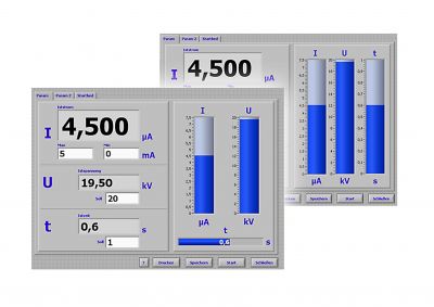
- Drivers, example programs, and programming manual
- Functions: high-voltage test, protective earth test, insulation test, current consumption test, 2-wire/4-wire, user interface, external relay matrix
- Compatible devices: UH36, UB36, UG36, RS36, ST400


- With magnetic switch
- With screw joint for connection of a cable socket
- For magnetic contacting

- Electrical Safety Tester Calibration (EST)
- HV test, earth bond test, ISO test
- Calibration of parameters: 3
- Calibration certificate in accordance to ISO 17025
- Repair service on request
- Devices: 36 & 400
- 4-pole (Sense/Source)
- PE plug: PES4
- Magnet contact
- Operation current: 32 A AC

- Remote control of Series 400 devices
- Create and edit test plans
- Menu-guided test plan selection: mouse/keyboard/scanner
- Administrator administration and user management
- Visualized test process and storage of reports
- Compatible devices: ST400
- Export formats: XML, PDF, CSV, HTML
- Remote control via: RS-232
- Languages: German, English
- Operating system: Windows

- Devices: 36 & 400
- 7-pole (Sense/Source/Good/Bad/24V)
- PE plug: PES7
- Magnetic contact plug
- Operation current: 32 A AC

- Devices: 36 & 400
- 4-pole (Sense/Source)
- PE plug: PES4
- Battery clamp
- Operation current: 32 A AC
- Devices: 36 & 400
- 4-pole (Sense/Source)
- PE plug: PES4
- Battery clamp
- Operation current: 32 A AC

- PE test lead, 4-pole, grey (D = 7.5 mm), with open cable end for self-assembly
- PE plug PES4, 4-pin, for plugging into the test instrument
- Max. operating current for PE tests: 32 A AC (source path)
- Selectable cable length: 2 m, 3 m or 5 m (other cable lengths on request)

- PE test lead, 7-pole, grey (D = 8.5 mm), with open cable end for self-assembly
- PE plug PES7, 7-pin, for plugging into the test instrument
- Max. operating current for PE tests: 32 A AC (source path)
- Selectable cable length: 2 m, 3 m, 5 m or 10 m (other cable lengths on request)
- Devices: 36 & 400
- 4-pole (Sense/Source)
- PE plug: PES4
- Battery clamp
- Operation current: 32 A AC


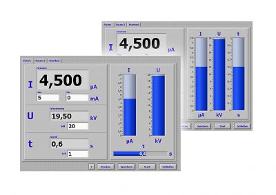
- Drivers, example programs and programming manual
- Functions: high-voltage test, protective earth test, insulation test, current consumption test, 2-wire/4-wire, user interface, external relay matrix
- Compatible devices: UH36, UB36, UG36, RS36, MR36, ST400