
Certified according to ISO 9001:2015
Certified quality management system
Certified quality management system

www.tuvsud.com/ms-zert


ST400 UGI-3030-1G
Product number:
64499
EAN:
4260689524907
Price on request
Goods expected soon
Details
Fachberatung unter
+49 421 277 9999
+49 421 277 9999
Print
Product information "ST400 UGI-3030-1G"
The ST400 UGI-3030-1G is a fully electronic test system for production and laboratory use with high-voltage (HV-DC) and insulation testing (ISO-DC). The test sequences are menu-driven, optionally manual or fully automatic, and can be implemented in five different operating variants (X2, X4, X5, X6, X8). Parameters, limit values, start options and operator instructions can be freely programmed; the device can be remotely controlled via Windows DLL, ASCII, .NET Framework Assembly, LabVIEW (via .NET) or DataView. If required, the system can be flexibly expanded by means of extension modules such as matrix, AC/DC sources or additional contacting.
Highlights
- Fully electronic test system for production and laboratory
- Menu-driven test sequences: manual or fully automatic
- 5 different operating variants freely selectable (X2, X4, X5, X6, X8)
- LAN, USB, RS232, CAN, VGA, DIGITAL-IN/OUT, Analog-IN/OUT, PROFINET RT, Frequency IO (depending on the operating variant)
- Test task freely programmable: parameters, limit values, start options, operator instructions, sequence options
- Remote controllable (Windows DLL, ASCII, .NET Framework Assembly, LabVIEW via .NET Framework Assembly, DataView, Digital IO)
- Expansion modules such as matrix, AC and DC sources, hot HV, contacting
- CE compliant, standards-compliant safety technology as required in EN 50191, the only system with TÜV-certified safety circuit up to PLe
Electrical tests: HV-DC & ISO-DC
High-voltage test HV-DC 3,000 V DC - 100 mA |
|
| Test voltage | |
| Setting range: | 150 - 3,000 V DC |
| Resolution, digit: | 1 V |
| Measurement uncertainty, accuracy: | 1% of measured value +/- 5 digits |
| DC voltage: | Rectified AC voltage, electronically generated |
| Voltage stability: | Output voltage electronically controlled, PI controller |
| Power, voltage control: | > 500 VA, incl. passive discharge and discharge monitoring |
| Ramp function: | freely programmable from 0.2 s to 6,000 s, incl. start voltage |
| Test current | |
| Setting range limit value: | 0.01 - 100.0 mA |
| Setting range minimum current: | 0.0 - 100.0 mA |
| Resolution, digit: | 0.01 mA |
| Measurement uncertainty: | 1% of measured value +/- 3 digits |
| Short-circuit current: | > 200 mA |
| Test time | |
| Setting range test time: | 0.5 s - 6,000 s, longer test time possible as an option |
| Setting range ramp time: | 0.2 s - 6,000 s |
| Resolution: | 0.1 s |
| Measurement uncertainty: | +/-10 ms |
| Start of test time: | The test time starts only after the test voltage has been fully reached |
| Miscellaneous | |
| Fault detection: | via Limit Detection, Peak Detection and Arc Detection |
| Measurement of current and voltage: | directly on the high-voltage side |
| Contact monitoring: | Monitoring of contact to the DUT with a suitable contacting device (4-wire) |
| Wire break monitoring: | Monitoring of the test leads for wire break |
| Automatic start test guns: | The start signal is triggered by pressing the test guns |
| Ground reference: | Floating, suitable for operation with test guns, in accordance with EN 50191 |
Insulation test ISO-DC 3,000 V DC - 1,000 MOhm |
|
| Test voltage | |
| Setting range: | 50 - 3,000 V DC |
| Resolution, digit: | 1 V |
| Measurement uncertainty, accuracy: | 1% of measured value +/- 5 digits |
| DC voltage: | Rectified AC voltage, electronically generated |
| Voltage stability: | Output voltage controlled, PI controller |
| Power, voltage control: | > 500 VA, fully electronic, incl. active discharge and discharge monitoring |
| Ramp function: | freely programmable from 0.2 s to 6,000 s, incl. start voltage |
| Resistance | |
| Setting range: | 0.20 - 1,000 MΩ |
| Measuring range 1: | 200.0 - 2,000.0 kΩ, resolution 0.1 kΩ, accuracy 1% of measured value at 500 V |
| Measuring range 2: | 2.000 - 20.000 MΩ, resolution 0.001 MΩ, accuracy 1% of measured value at 500 V |
| Measuring range 3: | 20.00 - 200.00 MΩ, resolution 0.01 MΩ, accuracy 1% of measured value at 500 V |
| Measuring range 4: | 200.0 - 1,000.0 MΩ, resolution 0.1 MΩ, accuracy 2% of measured value at 500 V |
| Test time | |
| Setting range test time: | 0.5 s - 6,000 s, longer test time possible as an option |
| Setting range ramp time: | 0.2 s - 6,000 s |
| Resolution: | 0.1 s |
| Measurement uncertainty: | +/-10 ms |
| Start of test time: | The test time starts only after the test voltage has been fully reached |
| Miscellaneous | |
| Measurement of current and voltage: | directly on the high-voltage side |
| Contact monitoring: | Monitoring of contact output to the DUT with a suitable contacting device (4-wire) |
| Wire break monitoring: | available as an option |
| Automatic start test guns: | The start signal is triggered by pressing the test guns |
| Ground reference: | floating, suitable for operation with test guns, in accordance with EN 50191 |
Housing, device data, environment & safety
Short housing |
|
| External dimensions (W x H x D): | 400 x 210 x 446 mm |
| Housing dimensions: | |
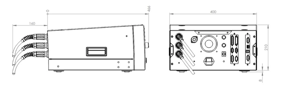 |
|
| Housing dimensions with right-angle connectors: | |
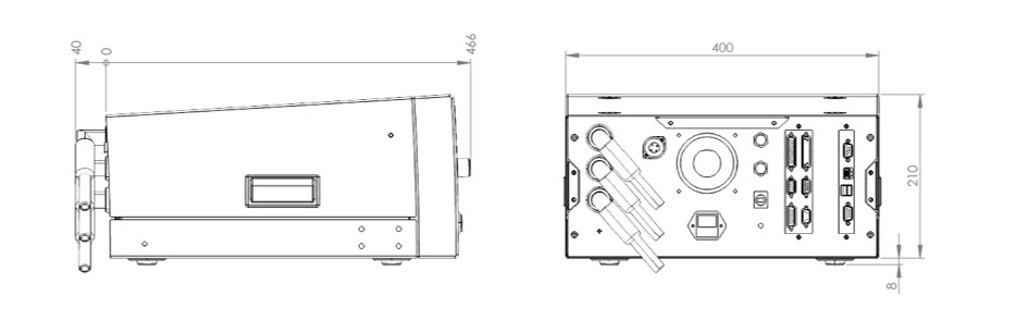 |
|
| Housing dimensions with 19-inch installation kit: | |
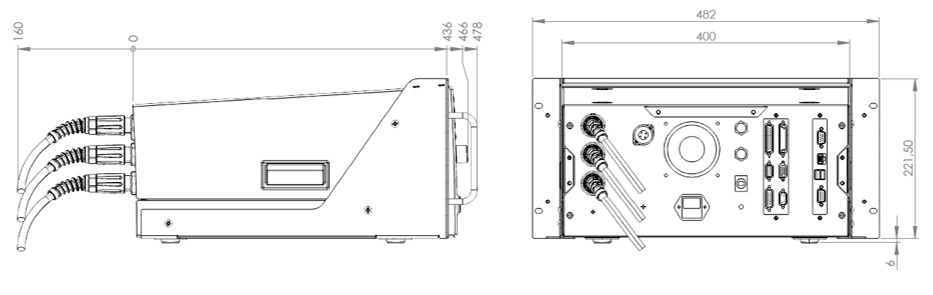 |
|
| Housing dimensions with 19-inch installation kit and right-angle connectors: | |
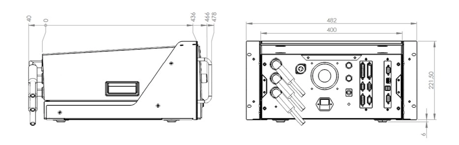 |
|
General device data |
|
| Input voltage: | 230 V, 50 Hz / 60 Hz |
| Mains connection: | Schuko plug, IEC appliance connector C14, vertical installation, 10 A, with fuse |
| Input voltage tolerance: | +/- 10% |
| Current consumption: | max. 10 A |
| Fuse: | 10 A, T, 5 x 20 mm, 250 V |
| Display: | X2 variant: no display, remote control variant X4 variant: 5.7" TFT color display with touch X5 variant: 10.4" TFT color display with touch X6 variant: no display, external monitor required X8 variant: 10.4" TFT color display with touch |
| Operating system user interface: | X2 variant: pure remote control variant X4 variant: WIN CE® X5 variant: WIN CE® X6 variant: WINDOWS® X8 variant: WINDOWS® |
| Saving test plans and results: | X2 variant: saving by higher-level control system X4 variant: optionally locally on SD card, optional USB or LAN X5 variant: optionally locally on SD card, USB or LAN X6 variant: optionally locally on hard drive, USB or LAN X8 variant: optionally locally on hard drive, USB or LAN |
| Setting the test parameters: | manual in the individual test menu or via test plan (DataView user interface) or fully automatic via interface (ASCII, DLL, .NET) |
| Fault signaling: | acoustic, visual and via interface |
| Basic equipment on delivery: | Operating instructions, power cable, safety circuit plug |
| Calibration: | Factory calibration incl. calibration certificate, DAkkS calibration optionally available |
| Housing: | Metal housing, RAL 7035 |
| Weight: | depending on the installed modules, 25 to 35 kg |
Ambient conditions |
|
| Housing: | IP20 |
| Humidity: | max. 80%, non-condensing |
| Permissible temperature range: | + 5 to + 40 °C |
| Max. height above sea level: | 2,000 m |
| Cooling: | active cooling |
Electrical safety and standards |
|
| EN 61010-1: | Safety requirements for electrical measuring, control, regulating and laboratory equipment |
| EN 61326-1: | Electrical equipment for measurement, control, regulation and laboratory use – EMC requirements |
| EN 61000-3-3 / EN 61000-3-2: | Electromagnetic compatibility (EMC) |
| EN 50191: | Setting up and operating electrical test systems |
| EN 60598-1: | Luminaires / Part 1: General requirements and tests |
| Pollution degree: | 2 |
| Protection class: | 1 |
Operation, start options & interfaces
Advanced device setup |
|
| User management: | individually configurable |
| Signal configurator: | individual configuration of the digital result outputs |
| File manager for test plans and results: | individual setting of storage options, storage location, naming of the result file and automated creation of result directories |
| Buzzer options: | individual configuration of the acoustic signals |
| Basic settings of the test system: | language selection, device name, interface configuration |
| Start of the user interface: | individual setting of the desired start menu (e.g. start directly in the test selection menu via barcode) |
| Test program selection: | manual via selection window, process-reliable via barcode or keyboard, via digital interface or by reading a transfer file |
| Manager for dummy test: | Dummy test is automatically requested according to configuration (e.g. at program start, when changing user, via digital interface, after a certain number of DUTs, at a specific time or after a time interval) |
| Interlock options for test cage: | individual setting of the interlock options (during the test, for pass, for fail, …) |
Start options for the test |
|
| Start and stop signal by test gun: | Special automatic start in 4-wire technique. The start of the test (switching on the test voltage) takes place only when both test guns are safely contacted (depending on the test types) |
| Start via safety circuit: | Start of the test takes place by closing the test cage |
| Start button on the device: | Start of the test takes place via button on the device front |
| Start via contact monitoring: | Start occurs only when contacting has taken place (source and sense connected) and no cable break is present – permanent monitoring |
| Start via serial interface: | Start takes place via higher-level control (PLC or PC) |
| Start via digital interface: | Start via digital IO such as PLC, foot switch, button, etc. |
| Start options: | individual setting of the start modes |
Interfaces |
|
| ETL interface / Digital IO: | Start, stop, PASS result, FAIL result and test running, and much more (all digital outputs are implemented with wear-free semiconductor components) |
| RS232 / LAN PC interface: | Remote control interface for customer-specific applications or for the ETL DataView data management package |
| CAN interface: | to expand the test system for additional features and further external expansion stages |
| LAN interface: | for connection to the customer's network, e.g. for storing test results, depending on the operating variant |
| USB port: | for connecting additional storage media as well as keyboard and mouse, depending on the operating variant |
| VGA port: | for connecting an external monitor, X6 and X8 variant only |
Connections - safety components |
|
| Signal lights: | Connection of a signal light combination (green/red) in accordance with EN 50191 |
| Safety circuit: | By means of appropriate wiring, customers can implement 3 different, standards-compliant safety circuits: testing with test guns, testing with safety test cage / two-hand operation, testing in an automation solution / production line |
| USER interface / Digital IO, optional: | digital interface for freely programmable inputs and outputs (all digital outputs are implemented with wear-free semiconductor components) |
| Analog IO, optional: | 4 analog inputs for capturing analog signals (0 - 10 V DC), 2 analog outputs (D/A), e.g. for result monitoring |
| Frequency IO, optional: | 4 frequency inputs for capturing speeds and their direction of rotation |
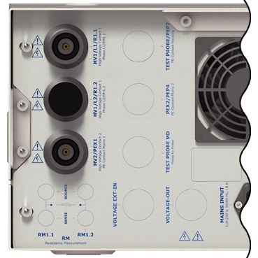
Device connections - for contacting the DUT (CC)
 |
|
| 2-pole HV socket: HV1 / L1 / R1.1 | DUT: connection L1 / L2 |
| 2-pole HV socket: HV2 / PEX | DUT: connection PE - mains connection |
Scope of delivery
- Operating instructions
- Power cable
- Safety circuit plug